Features
- Cyclone IV FPGA platform
The EP4CE6E22C8N supports hardware design projects ranging from basic logic to SOPC and Nios II development.
- Onboard memory and clock
Includes 64 Mbit SDRAM, 16 Mbit M25P16 configuration flash, and a 50 MHz oscillator.
- Built-in experiment hardware
Use the push buttons, LEDs, DIP switches, four-digit display, and buzzer for hands-on I/O projects.
- JTAG and Active Serial interfaces
Use JTAG to load SOF files and debug designs, or the AS interface to write configuration files to flash.
- Display, communication, and expansion interfaces
Access RS232, PS/2, VGA, a 20-pin LCD header, and expansion headers for external modules.
Overview
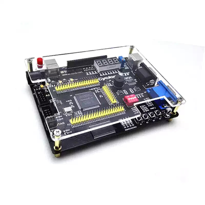
RZ-EasyFPGA A2.2 board
Build and test digital logic with the board's switches, indicators, and peripheral interfaces. The expansion headers let you add compatible displays, cameras, converters, or communication modules.

PCB layout and acrylic cover


Expansion and peripheral connections
Examples of direct expansion include LCD1602 and LCD12864 displays, serial ADC/DAC modules, and a 3.2-inch TFT. The all-in-one expansion board supports additional options such as OV7670 and OV5640 cameras, a 16-bit VGA module, USB and Ethernet modules, and compatible displays.


Specifications
| FPGA | Altera Cyclone IV EP4CE6E22C8N |
|---|---|
| PCB marking | RZ-EasyFPGA A2.2 |
| SDRAM | 64 Mbit (8 MB) |
| Configuration flash | M25P16, 16 Mbit (2 MB) |
| Oscillator | 50 MHz |
| Power inputs | 5 V power input and USB power input, with onboard source selection |
| Onboard regulator rails | 3.3 V, 2.5 V, and 1.2 V (1117 series) |
| Programming interfaces | JTAG and Active Serial (AS) |
| Controls and indicators | 4 user buttons, 1 reset button, 4 LEDs, 4-position DIP switch, and four-digit display |
| Audio and IR | Passive buzzer and infrared receiver |
| Temperature sensor | LM75A |
| EEPROM | AT24C08, I²C |
| Serial interface | RS232 via SP3232 |
| Display and peripheral connectors | Onboard VGA, PS/2, and 20-pin LCD header with contrast adjustment |
| Expansion | I/O header pins |
Applications
- Combinational logic, counters, decoders, and state machines
- Peripheral control with LEDs, keys, displays, and the onboard temperature sensor
- RS232, PS/2, I²C, and infrared experiments
- SOPC and Nios II prototyping
- Camera capture, traffic light control, and display experiments with the appropriate modules


FPGA example projects
The project list covers digital logic, peripheral control, displays, data conversion, SD card storage, and OV7670 camera capture. Some projects require additional modules.

Package Contents
Choose one of the seven packages below. The equipment shown in demonstration images depends on the package selected.
Board + USB Blaster
- 1 × FPGA development board with protective cover fitted
- 1 × USB Blaster programmer set
- 1 × infrared remote control
- 1 × USB power cable
2.4-inch Display + Expansion Board
- FPGA development board
- 2.4-inch display
- Expansion board
OV7670 Camera + Expansion Board
- FPGA development board
- OV7670 0.3 MP camera module
- Expansion board
Matrix Keypad + Traffic Light
- FPGA development board
- Matrix keypad and traffic light experiment hardware
5-Module Bundle + Expansion Board
- FPGA development board and programmer
- Expansion board
- USB module, network module, 2.4-inch display, OV7670 camera module, and VGA module
OV5640 Camera + VGA Bundle
- 1 × FPGA development board
- 1 × USB Blaster programmer set
- 1 × infrared remote control
- 1 × USB power cable
- 1 × all-in-one expansion board
- 1 × OV5640 5 MP camera module
- 1 × VGA module
VGA cable sold separately.
Standard Package in PP Box
- Standard FPGA development board configuration
- Polypropylene (PP) storage box
FAQ
How do JTAG and Active Serial differ?
JTAG loads an SOF file into the FPGA for testing and debugging. Active Serial writes a POF file into the configuration flash so the saved design can load after a power cycle.
Which camera is included with each camera package?
The OV7670 package includes a 0.3 MP camera and expansion board. The OV5640 Camera + VGA Bundle includes a 5 MP camera, all-in-one expansion board, and a separate VGA module.
Does the board already have a VGA connector?
Yes. The board has an onboard VGA connector. A separate VGA module is included with the 5-Module Bundle and the OV5640 Camera + VGA Bundle.
Connection & Operating Notes
The board provides separate 5 V and USB power inputs with onboard source selection. Check the power input and the header pin assignments before connecting an external module.
Programming ports and power inputs


No guides have been linked to this product yet.
Reviews
No reviews yet.